One of the first things any student pilot learns in ground school is how to read and interpret the instrument panel. Operating under visual flight rules (VFR), pilots rely primarily on outside references to navigate. And yet, having a solid understanding of flight instruments is essential for maintaining control, improving situational awareness, and preparing for more advanced maneuvers and operations.
At the heart of every aircraft’s instrument panel is the “six pack” – a set of primary instruments that provide critical flight data. Understanding these instruments is a key stepping stone for any aspiring aviator.
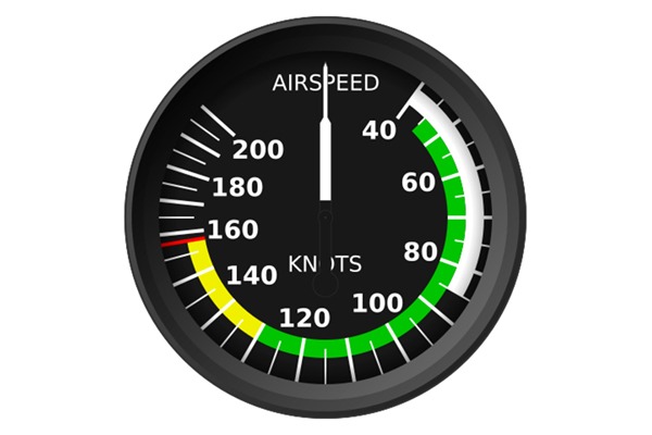
Airspeed Indicator (ASI)
The airspeed indicator measures the aircraft’s speed through the air, typically in nautical miles per hour, or knots. By calculating dynamic pressure between the pitot tube (located on the wing) and static port (typically on the side of the airplane), this instrument is critical for safe takeoffs, landings, and stall prevention.
While obviously helping pilots determine their speed through the air, the airspeed indicator displays other helpful information. The green arc of the display represents the normal operating range for the aircraft, with the bottom end of the arc representing the speed at which wings will stop producing lift. The yellow arc denotes the structural warning area – speeds at which abrupt movements are discouraged. The red radial line is the never-exceed speed, the point of which a pilot risks catastrophic failure or damage to the aircraft structure. Finally, the white arc is the flap operating range, with the bottom of the arc representing the speed at which wings stop creating lift with flaps configured.
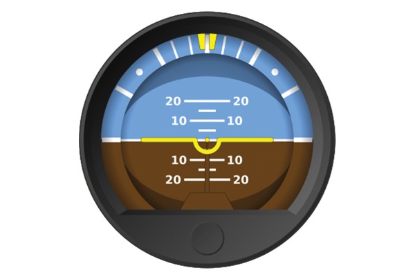
Attitude Indicator (AI)
Also known as the artificial horizon, the attitude indicator provides an immediate visual reference for the aircraft’s orientation relative to the horizon, displaying both pitch (nose-up or nose-down) and bank angle. While pitch is marked by horizontal lines typically in 5° increments, hash marks along the top, outer portion of this instrument denote bank angles of 10°, 20°, 30°, 45°, and 60°.
With humid days (or even wildfires) bringing hazy skies that obscure the horizon, this is certainly one of the more often referenced instruments. Student pilots will also train with unusual attitudes, which trick the body’s senses, causing spatial disorientation. In times like this, pilots will quickly recognize the importance of the attitude indicator.
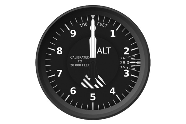
Altimeter
The altimeter measures the aircraft’s altitude above mean sea level (MSL) by sensing atmospheric pressure changes through the aircraft’s static system. Combined with ground levels denoted on sectional charts, pilots can determine proper separation from terrain and in avoiding other aircraft.
Temperature and other factors can greatly influence atmospheric pressure, and pilots in training will learn early on to check local weather reports to determine what setting the altimeter needs to be set at in order to display accurate information during flight.
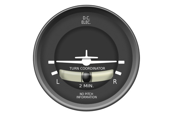
Turn Coordinator
The turn coordinator provides information about the aircraft’s rate of turn and whether the turn is coordinated (balanced use of rudder and aileron). In actuality, it is really two instruments in one!
Hash marks at the sides mark a standard-rate turn (3° per second), which would bring a plane around in a full circle over the course of two minutes. The inclinometer, which looks like a level display, shows if the aircraft is in coordinated flight. This helps reduce drag, improve efficiency, and prevents unintentional skids or slips (something we’ll cover in a future post) that could lead to loss of control.
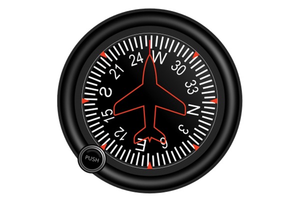
Heading Indicator (HI)
The heading indicator displays the aircraft’s direction in degrees relative to magnetic north. While it is not a compass, the greatest advantage to using the heading indicator is its stability. The magnetic compass is a great tool, but interference from radios and electronics, along with errors during acceleration/deceleration and turns must be accounted for.
While pilots adjust the heading indicator to match the magnetic compass during stable flight, it is gyroscopic and is not easily affected by outside forces.
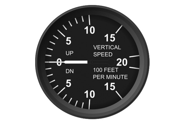
Vertical Speed Indicator (VSI)
The vertical speed indicator shows the rate at which an aircraft is climbing or descending, most often measured in feet per minute (fpm). In utilizing this instrument, pilots can ensure smooth climbs and descents, helping maintain altitude, discipline, and fuel efficiency.
Even though VFR pilots are trained to operate with their view primarily outside of the cockpit, quick scans of these instruments can confirm the positioning of the aircraft as it traverses the skies above.
At DreamFlight Charities, we believe in making aviation education accessible to all. Our free ground school materials help aspiring pilots build a strong foundation in aviation concepts. Be sure to check out additional resources and discover our many programs and services designed to help students take the next step in their aviation journey.